Define Pit/Dump Regions

Defining pit slope regions and rosettes

Define Pit/Dump Regions

To access this dialog:

  • Activate the Design ribbon and select Pit Modelling | Define Slopes. The Define Regions panel is shown by default.

  • Activate the Design ribbon and select Dump Modelling | Define Slopes. The Define Regions panel is shown by default.

note.gif (1017 bytes)

This panel is used for the definition of both pit and dump slope and berm width regional settings. Unless otherwise stated, the terms pit and dump are synonymous, as are bench and lift.


This panel is used to extract, edit and/or define the slope specifications for your pit or dump. This is achieved using a combination of the following specifications:

  • Regions - high-level spatial references for your pit as determined by manual construction of face angle and berm widths, data extracted from a nominated attribute in the input planning model or previously-defined geotechnical boundary strings.

    Differences between regional settings (face angle, width, rosette influence) will be managed during automated pit design, using the Conditioning tab, where a blending distance between regions can be set.

    Regions can be defined by either manually constructing a table of region names and angles/widths, or you can extract zone information according to the specified planning model (pit definitions only) or you can choose to define your regions using closed and distinct boundary strings that contain an attribute referencing a region.

    Region names can be set or imported as either numeric or alphanumeric data.

    When importing region data, the contents of the selected file will be validated to ensure that at least one region can be formed. Open string data will be ignored and the corresponding Region ID attribute value will not be listed if all strings carrying that attribute value are open. Otherwise, if at least one closed string is detected, the corresponding Region ID attribute will be listed in the drop-down menu and can be used to define a slope region.
  • Rosettes - optionally, lower-level details applying to a particular elevation and azimuth for a given region. Each region can be further controlled using one or more rosettes. For a nominated elevation range (From Z to Z), and azimuth limit, an expected face angle and berm width (either standard or catch type) is specified.

Initially, you define the spatial reference for your slope region. Define each region and default values, then any additional width and angle specifications (per region) using rosette definitions for finer control.

Once a region has been defined, with or without rosette support (without = region-level slope definitions are applied regardless of azimuth), it can be assigned to a bench (or bench group) reference within the pit, using the Bench/Lift Constraints panel. As both Standard and Catch berm widths are defined separately, the appropriate width will be assigned according to the defined berm type.

Note that the azimuth values represented within each rosette indicate the azimuth of the face within a nominated region. Where a pit contour sweeps across a severe angle change over a short distance (e.g. such as with a dog-leg effect), the range of angles can be quite high (e.g. over 90 degrees). The face angle and berm width are therefore applied according to the azimuth of the face. The overall aim of rosettes is to ensure pit or dump stability.

Rosettes

Slope regions can optionally include one or more rosettes. Rosettes comprise a location and a set of azimuths each of which has a set of the three standard control values (face angle, standard and catch berm widths).  

Rosettes have a minimum and maximum elevation to define their volume of influence. The horizontal influence of a rosette covers the entire slope region in which it is contained.  

Each rosette is given an X, Y location. The X, Y location is only used when multiple rosettes are being used to interpolate the projection values a string point.

How Rosettes Work

When using a single rosette to determine the projection control values at a point, the direction azimuth of the projection is used to locate the corresponding azimuth in the rosette. The X,Y location of the rosette is NOT used.  The elevation constraints are always used.

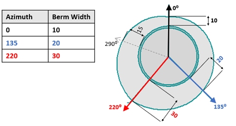
In the diagram below a circle is being projected using the rosette parameters in the table. If a point is being projected at an azimuth of exactly 0⁰ the berm width is 10. If a point is projected at an azimuth of 220⁰ the berm width is 30.   

There is a gradual change in berm widths between the specified azimuths. If a point is being projected at 290⁰ the berm width will be 15, i.e. mid-way between 0 and 30.

Face angle values are determined using the same methodology for berm widths as described above.

 Multiple Rosettes and Interpolation of Control Values

For pits or dumps in more advanced stages of design it is common for slope regions to contain at least one rosette, for example to force temporary internal walls to have a shallower angle than final walls which due to their longevity warrant the extra cost of being blasted using pre-splitting.

For more complex geotechnical configurations, or perhaps in an early study using a single default slope region, multiple rosettes may be used. In this case an interpolated value at a projection point is calculated by using each of the relevant rosette values.  

The influence of each rosette can be adjusted by assigning it an inverse distance weighting (IDW Power value) which is used in the interpolation. If no IDW Power value is assigned then nearest neighbour interpolation is used.

Rosettes Reminders

  • The X,Y location of a rosette is only relevant when interpolating values from multiple rosettes.
  • The direction of projection of a point is used to determine the corresponding rosette azimuth values. A single point on a design string may have up to 2 projection directions: one for each of the adjacent edges.
  • The X,Y location of a rosette may be outside the volume of the slope region in which it is being used.
  • Each rosette belongs to a single slope region

Modifying Table Contents

Each of the tables displayed on this form behave in a similar manner. To add a new data row, enter your data into the bottom row and click the green "+" button. At this point, if there is a problem with any data you have entered, you will be shown a message highlighting the problem (for example, you have entered a negative value where it isn't permitted).

To remove an existing table row, click the red "x" button.

As with all managed tasks, updates made on this panel are committed to the Database using the Save (1) or Save and Close (2) buttons at the top of the form.


Field Details:

Pit/Dump: select the pit to which the current slope region definition applies.

If defining pit regions, this list contains all pits defined using the Reserves ribbon's Manage task.

If defining dump regions, this list contains all dumps defined using the Define Dumps task.

Region Reference: regions are defined using data from either of the following:

  • Manual: a manual definition of spatial references within the pit - slope regions and berm widths will be defined solely on manual data input into the tables below, and theBench Constraintspanel.
  • Planning model (pit regions only, not available for dumps): information held in the currently-defined planning model (Setupribbon |Model | Define- note that the planning model must be defined beforehand - it cannot be selected as part of theRegions and Rosettestask). The currently-defined planning model is displayed in theFilefield (read-only). You can create an automatically indexed table based on unique model attribute values by selecting an attribute from the Region ID drop-down list.

    For example, a REGION attribute could be defined within the planning model, containing 5 unique values. After selecting the REGION attribute, the Slope Region table will update to show 6 table rows; 1 DEFAULT row and 5 others representing each distinct region. From there, you need to populate the table with Face Angle and Berm Width details.

    You can define an attribute in your planning model by setting the "Slope Region" assignment for the appropriate attribute, using the Define Planning Model task.
  • Boundary Strings: strings representing region extents. A boundary strings file should contain closed and non-overlapping strings to define distinct boundaries. Each string entity within the file must be differentiated by an attribute (this can be any data field).

    When importing region data, the contents of the selected file will be validated to ensure that at least one region can be formed. Open string data will be ignored and the corresponding Region ID attribute value will not be listed if all strings carrying that attribute value are open. Otherwise, if at least one closed string is detected, the corresponding Region ID attribute will be listed in the drop-down menu and can be used to define a slope region. If a combination of open and closed strings are detected for a given Region ID, a message will be broadcast to the Output control bar, for example:

    Region string file C:\MyDirectory\MyStrings.dm contains some open strings. These cannot be used to define regions, and have been ignored. The open strings define the following regions: REGIONA, REGIONB

    In the example, below, a boundary string object containing 2 closed strings (differentiated by a ZONE attribute) has been loaded. Zone 1 and Zone 2 have been defined with different berm width and face angle. The image below shows the impact of applying this type of regional control to the resulting generated pit (using the Recalculate option in the Auto Design task):


    The same principle applies to dump regions; select the boundary string representing a plan view of regions. Where the dump falls within a boundary (and a region definition exists), the corresponding lift face angle and berm width(s) will be applied.

    For more information on controlling the blend between regions, refer to String Conditioning.

    For boundary string-based regions (only), string data is converted into a collection of points arranged in a grid so that blending can be applied between regions of differing slope settings. By default a grid will be created with a 10m spacing. This setting is controlled using the Grid Spacing field.

    For example, the image on the right below shows the effect of a 10m grid spacing for the same region string control as shown above (a pit is displayed, but the same principle applies to dumps). The image on the left shows a grid spacing of 100m. Note that the blending Distance between regions (as set in the Auto Design task) is set to 100m at the pit level so applies to both cases. The result is that, whilst blending is applied between regions in both cases, the resolution of the grid used to control the smoothing is lower in the 100m grid spacing case, resulting in the introduction of unwanted string artefacts (in this case):


    Reducing the grid spacing for boundary string slope control will increase the processing time required for generating design strings in the Auto Design tasks for pits and dumps. This is because more points of influence need to be considered during blending between regions.

If using a planning model or boundary strings to define regions, an attribute within the selected file will be used to populate a table definition containing region information. Once selected, the Region table below is populated with relevant Name data (all unique values within that attribute will be extracted, other than absent data).

Region (table): this table is used to define each slope region within the nominated pit, and for each region the corresponding face angle, berm width and (optionally) inter-ramp angle value.

In fact, two berm widths can be defined; one for Normal berms and another for a special case Catch berm (otherwise known as a safety or geotechnical berm). You get to choose which of the berm widths is used on the Bench/Lift Constraints panel. You can, if you wish, define an inter-ramp angle instead of a width for either the standard or catch berms (updating the inter-ramp angle will automatically update the corresponding width and vice versa).

If you wish to specify (or view) the inter-ramp angles for each region, enable the Show inter-ramp angle assuming a bench height of check box is enabled. You will need to enter a positive bench height. The calculation is then performed according to the order of the columns in the table above, with the left most column being preserved.

For example, region 1 has a face angle of 45 degrees and berm width of 15 meters.

  • A Face Angle of 45 degrees is set. Where Berm Width is the leftmost table column, If inter-ramp angles are enabled, the IR Angle field for a bench height of 10 meters is calculated as 21.8 degrees. In this situation, the Berm Width value remains static and the IR Angle is (re)calculated.

  • A Face Angle of 45 degrees is set. Where IR Angle (Standard) is the leftmost table column, If inter-ramp angles are enabled, the IR Angle field for a bench height of 10 meters is specified as 25 degrees. In this situation, the Berm Width value is calculated as 17.17 degrees.

You can change the position of the columns in the region table by left-clicking and dragging the respective header cell to its new position.

In summary, the following table columns are possible in the Region table, for each region (note that the order of columns may be different to the order shown below):

  • Region: a unique label representing a slope region. A DEFAULT entry will always exist and must have (at least) Face Angle and Berm Width defined. Alphanumeric string.

  • Face Angle: the angle formed by connecting the crest of a pit bench and the toe of the bench immediately below. This will be dictated by rock strength, structural fabric and blasting parameters.

  • Berm Width (Standard): the distance between the toe and crest of a bench.

  • IR Angle (Standard) : the angle between the toe of a slope where a ramp segment passes and the toe of a bench located immediately upwards. Only displayed if the Show inter-ramp angle... check box is selected.

  • Berm Width (Catch): the catch bench (“CB”) or berm is used to catch spalling rock and prevent it from rolling down the pit wall, creating a safety hazard.  A rule of thumb is that the catch bench width should be according to the formula 4.5m + 0.2H, where H is the height of the bench. This means the recommended catch bench width for a 5m high bench should be about 5.5m; for a 10m high bench it should be 6.5m; and for 15m high bench it should be 7.5 metres.the distance between the toe and crest of a bench.

  • IR Angle (Catch) : for any catch bench, the angle between the toe of a slope where a ramp segment passes and the toe of a bench located immediately upwards. Only displayed if the Show inter-ramp angle... check box is selected.

If regions have been manually-defined, they may be deleted using the Delete button at the end of their row. If regions have been extracted from the planning model or boundary string file, they cannot be removed using this panel; these edits will need to made to the specified model or string file beforehand.

A DEFAULT value will always be at the top of the table - this can be considered the "pit- or dump-level" slope definition, which will be used for all pit benches that are not allocated to any other pit region/rosette or manual override. A pit or dump must have default values for Face Angle and Berm Width as these values will be used in the absence of other regional slope information. In fact, you cannot save the task unless the DEFAULT table row contains numeric data entries in these two columns. Catch berm widths are optional.

Selected Region Rosettes: when a region is selected in the Region List (see above), its current rosette information is listed here. New rosettes may be explicitly added by typing into the empty first row. Rosettes may be deleted using the delete button at the end of their row. All entries in the rosette are editable. X and Y can only be numeric. Z Min and Z Max can be numeric or absent.

  • IDW Power: the "strength" of a rosette relates to the size of the zone over which it can influence slope angles and/or berm widths. The higher the value, the larger the zone of influence the specified rosettes with a particular region will have. Negative values are not permitted.

    In other words, the influence of each rosette can be adjusted by assigning it an inverse distance weighting (IDW Power value) which is used in the interpolation. If no IDW Power value is assigned then nearest neighbour interpolation is used.

  • Add from View: allows a new rosette to be created at a location selected interactively in the 3D or Design views.

  • Select from View: will display indicators for all the rosettes in the 3D or Design views, and allow the rosette to be chosen by clicking on the indicator in the 3D or Design view.

More about Geotechnical Control in Automated Pit/Dump Design...

Selected Rosette Details: for each rosette, define:

  • A maximum Azimuth (from 0 or the previously-defined Azimuth) to which rosette-driven regional constraints apply.

  • A Face Angle to apply when a design is within the region of influence of the rosette.

  • A Berm Width to use within the pit design under the influence of the rosette. As for region-level data, you can specify Normal and/or Catch berm widths independently. You can delete a rosette azimuth definition using the button on the far right of the respective table row.

  • IR Angle (Standard/Catch): If the Show inter-ramp angle... check box (see above) has been selected, you will also be able to define or view (depending on the left-right order of the table columns) the inter-ramp angle for standard and catch berms. As with the region-level constraints, the specified bench height will be used to calculate either the IR Angle (if IR Angle is to the right of the Berm Width column) or the Berm Width (if Berm Width is to the right of the IR Angle column).

Rosette values are linearly interpolated between reference azimuths, and the shaded zones will also follow this interpolation.

  • Top-down or Bottom-up radio buttons changes the visualization accordingly.

    Top-down assumes a circular pit or dump rim and berm offsets, face offset and impression of the pit bottom. Bottom-up starts with a circular pit or dump base and works up to a non-uniform pit rim.

  • Bench Height: edit this integer to see the impact of differing bench or lift heights on the rosette projection above - note that this will not adjust the existing bench table - it is purely illustrative.

More about Geotechnical Control in Automated Pit/Dump Design...

  openbook.gif (910 bytes)   Related Topics


Open Pit Mine Design
Regions and Rosettes
Define Bench Constraints
Reserves - Manage Pit
Define Planning Model
Auto Pit Design